
The construction of wooden floors between floors: detailed construction technology
During the construction of private low-rise buildings of wood, concrete blocks or bricks, floors are most often erected between floors. These designs, in comparison with alternative concrete slabs, have several advantages. Wooden floors do not overload the walls, during installation do not require the use of lifting equipment. In addition, they have high strength, durability and reasonable price. Installation of such ceilings is quite simple, so many home masters perform it themselves.
Content
Floor structure
The basis of the wooden floor is the beams that are held on the supporting walls and serve as a kind of "foundation" for the remaining structural elements. Since the beams during the operation of the floor will bear the entire load, special attention should be paid to their competent calculation.
For beams, they usually use massive or glued beams, logs, sometimes boards (single or fastened in thickness with nails or staples). For floors, it is desirable to use beams made of coniferous species (pine, larch), which are characterized by high bending strength. Hardwood bars work much worse in bending and can deform under load.

Draft boards (OSB, plywood) are fixed to the floor beams on both sides, on top of which the front coating is sewn. Sometimes the floor of the second floor is laid on the logs, which are fixed on the beams.
It is worth remembering that the wooden floor from the side of the first floor will be the ceiling, and from the side of the second floor (attic, attic) - the floor. Therefore, the upper part of the floor is sheathed with floor materials: sheet pile, laminate, linoleum, carpet, etc. The lower part (ceiling) - clapboard, drywall, plastic panels, etc.
Due to the presence of beams, space is created between the rough boards. It is used to give overlapping additional properties. Depending on the purpose of the second floor, thermal insulation is laid between the floor beams
In the event that the second floor is a non-residential attic that will not be heated, thermal insulation must be laid in the ceiling structure. For example, basalt cotton wool (Rockwool, Parock), glass wool (Isover, Ursa), polystyrene, etc. Under heat insulation
If EPPS, which does not absorb water vapor, was used as thermal insulation, the vapor barrier film from the “pie” can be excluded. Thermal insulation
If the second floor is planned as a heated and residential building, then the “pie” of the floor does not need additional thermal insulation. However, in order to reduce the impact of noise that will occur when people move along the floor, soundproofing is laid between the beams
For example, basalt cotton wool (Rockwool, Parock), glass wool (Isover, Ursa), foam, sound absorbing panels ZIPS, soundproof

Fixing the beams to the wall
Beams can be connected to the walls in several ways.
In brick or timber houses, the ends of the beams are led into grooves (“nests”). If bars or logs are used, then the depth of the beams in the walls should be at least 150 mm, if the boards - at least 100 mm.
Parts of the beams in contact with the walls of the "nest" are waterproofed, wrapping them with two layers of roofing material. The ends of the beams are cut off at 60 ° and left uninsulated
When entering a “nest”, ventilation gaps of 30-50 mm are left between the beam and the wall (from all sides), which are filled with thermal insulation (tow, mineral wool). The beam is supported on the base of the groove through an antiseptic

In wooden houses, beams are buried in the grooves of the walls by at least 70 mm. To prevent the appearance of squeaks, waterproofing is made between the walls of the groove and the beam
Also, the beams can be fixed to the wall using metal supports - steel corners, clamps, brackets. They are connected to the walls and beams with self-tapping screws or screws. This mounting option is the fastest and most technologically advanced, but less reliable than when joining the beams in the grooves of the walls.

Calculation of floor beams
When planning the construction of the floor, first you need to calculate the design of its foundation, that is, the length of the beams, their number, optimal cross section and step location. It will depend on how safe your floor will be and what kind of load it can withstand during operation.
Beam Length
The length of the beams depends on the width of the span, as well as on the method of fastening the beams. If the beams are fixed on metal supports, their length will be equal to the span. When filling in the grooves of the walls, the length of the beams is calculated by summing the span and the depth of the two ends of the beam into the grooves.
Beam spacing
The distance between the axes of the beams is kept within 0.6-1 m.
Number of beams
The calculation of the number of beams is performed as follows: they plan to place the extreme beams at a distance of at least 50 mm from the walls. The remaining beams are placed in the span space evenly, in accordance with the selected interval (step).
Beam section
Beams can have a rectangular, square, round, I-section. But the classic option is still a rectangle. Frequently used parameters: height - 140-240 mm, width - 50-160 mm.
The choice of the beam cross section depends on its planned loading, span width (on the short side of the room) and the spacing of the beams (step).
The beam load is calculated by summing the load of its own weight (for floors - 190-220 kg / m2) with temporary (operational
The beams are laid along a short span, the maximum width of which is 6 m. At a larger span, the beam sag is inevitable, which will lead to deformation of the structure. However, in such a situation there is a way out. To maintain the beams on a wide span, columns and supports are installed.
The beam section directly depends on the span width. The larger the span, the more powerful (and strong) the beam must be selected for overlap. The ideal span for overlapping beams is up to 4 m. If the spans are wider (up to 6 m), then it is necessary to use non-standard beams with an increased cross-section. The height of such beams should be at least 1 / 20-1 / 25 of the span. For example, for a span of 5 m, you need to use beams with a height of 200-225 mm and a thickness of 80-150 mm.
Of course, it is not necessary to independently perform beam calculations. You can use ready-made tables and diagrams that indicate the dependence of the size of the beams on the perceived load and the span.

After performing the calculations, you can proceed to the device overlap. Consider the whole process, from fixing the beams to the walls and ending with the finish sheathing.
Wood flooring technology
Stage # 1. Installation of floor beams
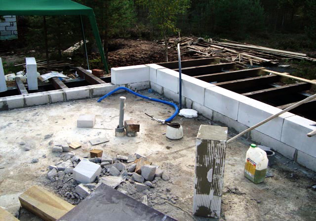
Most often, beams are installed with their institution in the grooves of the walls. This option is possible when the installation of the floor is carried out at the construction stage of the house.
The installation process in this case is as follows:
1. Beams are coated with antiseptics and flame retardants. This is necessary to reduce the tendency of wooden structures to rot and ensure fire safety.
2. The ends of the beams are cut at an angle of 60 °, they are painted with bitumen mastic and wrapped in 2 layers of roofing material (for waterproofing). In this case, the end must remain open, for free exit through it of water vapor.
3. Begin installation with the installation of two extreme beams, which are placed at a distance of 50 mm from the walls (minimum).
The bars are brought into the “nests” of 100-150 mm, leaving a ventilation gap between the wood and the walls of at least 30-50 mm.
4. To control the horizontal position of the beams, a long board is installed along their upper plane onto the rib, and a bubble level is placed on top of it. To level the beams, use wooden dies of different thicknesses, which are laid in the lower part of the groove on the wall. Dies must first be treated with bitumen mastic and dried.
5. To eliminate the creak of the beam and block the access of cold air, the gap is filled with mineral insulation or tow.
6. On the laid control board lay out the rest, intermediate, beams. The technology of their installation in the nests of the walls is the same as when installing the extreme beams.
7. Each fifth beam is additionally fixed to the wall with an anchor.

When the house is already built, it is easier to install the beams for the ceiling with the help of metal supports. In this case, the installation process is as follows:
1. Beams are impregnated with flame retardants and antiseptics.
2. On the walls, at one level, in accordance with the calculated step of the beams, fix the supports (corners, clamps, brackets). Fastening is performed with screws or screws, screwing them into the holes of the supports.
3. Beams are laid on supports and fixed with self-tapping screws.
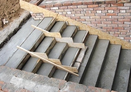
Stage # 2. Fixing cranial bars (if necessary)
If it is more convenient to lay a “cake” of the ceiling structure from above, that is, from the side of the second floor, cranial bars with a cross section of 50x50 mm are stuffed on the edges of the beams on both sides. The lower part of the bars should go flush with the surface of the beams. Cranial beams are necessary in order to lay on them the strip boards, which are the rough basis for the ceiling.
No cranial bars can be dispensed with if the hemming boards are hemmed from below, from the side of the first floor. In this case, they can be attached directly to the beams, using self-tapping screws (nails do not fit, since it is difficult to hammer them vertically into the ceiling).
Stage # 3. Fastening of roll-up boards for a rough ceiling base
When mounting from the side of the second floor on cranial bars with nails or self-tapping screws, fastening boards are fixed (it is possible to use OSB, plywood).
When fastening the run from the side of the first floor, the boards are fixed to the beams from below using self-tapping screws. If necessary, lay a thick layer of insulation between the beams or soundproof
Stage # 4. Installation of vapor barrier (if necessary)
The vapor barrier is laid in the ceiling structure in front of the insulation (which can also act as a sound absorber) if there is a risk of steam entering it or condensation. This happens if the overlap is arranged between floors, the first of which is heated, and the second is not. For example, an unheated attic or attic is arranged above the first residential floor. Also, steam can enter the floor insulation from wet rooms on the first floor, for example, from a kitchen, bathroom, pool, etc.
A vapor barrier film is laid over the floor beams. The canvases are lapped, leading the edges of the previous canvas to the next by 10 cm. The joints are glued with construction tape.
Stage # 5. Thermal insulation or sound insulation
Between the beams, plate or roll heat or sound insulators are laid on top. Slots and voids must be avoided; materials must fit snugly against the beams. For the same reason, it is undesirable to use trimmings that have to be joined together.
To reduce the occurrence of shock noise in the ceiling (with a residential upper floor), soundproofing strips with a minimum thickness of 5.5 mm are laid on the upper surface of the beams.
Stage # 6. Waterproofingth film
Heat or sound insulating
Waterproofing
Stage # 7. Fixing boards (plywood, OSB) for the subfloor
On the beams from above, a draft basis for the floor of the second floor is sewn. You can use regular boards, OSB or thick plywood. Mounting is performed using self-tapping screws or nails.
Stage # 8. Covering the bottom and top with topcoats
Any suitable materials can be laid on top of the rough base from the bottom and from the top of the floor. On the upper side of the floor, that is, on the floor of the second floor, they arrange coatings of laminate, parquet, carpet, linoleum, etc. When arranging the floor of a non-residential attic, draft boards can be left without sheathing.
Ceiling materials are sewn on the lower surface of the ceiling, which serves as the ceiling for the first floor: wooden lining, plastic panels, drywall constructions, etc.

Floor operation
If the design used beams with a large margin of safety, laid with a small pitch, then such an overlap will not need repair for a long time. But still you need to check the strength of the beam regularly!
If the beams are damaged by insects or as a result of waterlogging, they are strengthened. To do this, the weakened beam is removed, replaced with a new one or reinforced with durable boards.
4 comments